|
Corresponding author: Valery P. Bereznev ( bvp@ibrae.ac.ru ) Academic editor: Yury Kazansky
© 2018 Evgeny F. Seleznev, Valery P. Bereznev.
This is an open access article distributed under the terms of the Creative Commons Attribution License (CC BY 4.0), which permits unrestricted use, distribution, and reproduction in any medium, provided the original author and source are credited.
Citation:
Seleznev E, Bereznev V (2018) Application of diffusion approximation in the calculations of reactor with cavities. Nuclear Energy and Technology 4(3): 203-209. https://doi.org/10.3897/nucet.4.31863
|
Abstract
The importance of calculation of radiation fields inside in-reactor cavities is associated with the necessity to simulate the emergency modes in fast breeder reactors (FBR), as well as reactor states with different coolant levels in special dedicated channels of passive feedback devices in lead-cooled fast reactors (LFR) of BREST type or in sodium cavities in sodium-cooled fast reactors (SFR).
The Last Flight (LF) method (
In addition, it is desirable to implement the cavities calculation methodology within the framework of the approximations used in reactor calculations introducing certain specific features. In particular isotropy of the neutron flux density and the necessity of forced introduction of a “conditional” calculation cell on the boundary surface of the void cavity are assumed in the diffusion approximation. If the LF method is oriented on the connection of the source point with the detection point, then it is necessary to determine in the calculation of neutron field in the cavities the neutrons escaping the surface area of the source and neutrons reaching a certain surface area of the cavity. In order to solve the problem, the authors suggested using the approximate solution presented in the paper.
Thus, an algorithm for calculation of in-reactor cavities using the diffusion approximation was developed and implemented by the authors.
Keywords
Fast breeder reactor, diffusion approximation, cavities calculations.
Introduction
Neutron transport in steady-state conditions in the fast reactor core can be described, for instance, in multi-group diffusion approximation as follows:

where Фg (r) is the neutron flux density; Dg (r) is the diffusion factor; Σgr (r) is the removal cross-section; Σl→g (r) is the cross-section of neutron transfer from group l to group g; χg is the fission neutron spectrum; νΣgf (r) is the neutron multiplication cross-section; Q (r) is the intensity of the external neutron source.
The main advantage of the diffusion approximation for practical implementation in computer codes is the high speed with which the solution is obtained and low requirements on the availability of computational resources. Nevertheless, certain applicability limits exist posed by the presence of strongly absorbing medium and pronounced spatial heterogeneity.
In particular, diffusion approximation is not applicable in the presence of gaseous (vacuous) medium. Methods for calculating radiation in such media can be based on the solution of integral neutron transport equation. If the purpose is to define radiation field outside the calculation area, then the last flight method (LF) is widely applied. However, in practice this method is not easily applicable for calculating internal cavities, since uncertainty of the method is high at the distances close to the surface. In such case volume sources used in LF-method can be replaced with surface sources with subsequent numerical integration over the surface separating dense and gaseous media.
Thus, the purpose of the present study is to create combined algorithm with associated calculation module converging the diffusion approximation producing fast solution with semi-analytical solution of integral equation inside in-reactor cavities.
Algorithm for calculating unscattered component
Linear integrodifferential neutron transport equation can be written in the following integral form:
 (1)
(1)
Equation (1) means that neutron flux φ(r, Ω, E, t) in point r is caused by neutrons which appeared in all points r–s′Ω with direction Ω and energy E for all positive s′. Exponential multiplier here is the attenuation factor characterizing the reduction of neutron flux when s = 0 is reached, and Σ(r–s′′Ω, E) is the total macroscopic cross-section of neutron interaction with medium. Integration over s′ can be achieved only within the boundaries of the area under examination if incoming neutron flux is absent.
We suggest spreading such representation of the solution only on “vacuous” calculation cells filled with gaseous medium where density of the matter is low to such extent that cross-sections of neutron interactions with medium are very small, so that diffusion factor exceeds by several orders of magnitude its values in a typical reactor medium, and not allowing using conventional diffusion approximation in the medium in question.
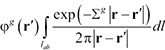
As it was indicated in (
 (2)
(2)
where integration is performed over the surface separating dense and gaseous media; exp(– Σg|r – r′|)/(4π|r – r′|2) is the probability for neutron from r to reach r′ without collisions; φg (r′)dS′ is the field from the surface element dS′; φg (r) is the field in r due to the field from surface S′. Multi-group energy approximation to which index g corresponds is used in expression (2) and hereafter.
Let us examine transmission of radiation using two-dimensional model of hexagonal calculation cell conventionally applied in the FBR calculations as represented in Figure

 (3)
(3)
where integration is performed along the plane AB; φg (r) is the field in point r taking into account radiation coming from only the AB plane.
Average value of field on the “receiving” plane ab taking into account (3) and rearrangement of the order of integration is as follows:
 (4)
(4)
In such case the value
 (5)
(5)
is the contribution in the field on the plane ab made only from the field in point r′ located on the plane AB.
Assuming that field on the plane AB is the same for all its points, i.e. that φg (r′) = φgAB, and y – y′=const=Δy in accordance with Fig.
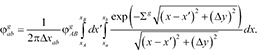 (6)
(6)
The obtained integral can be calculated approximately and, in case of gaseous medium (Σg ~10–4 cm–1), Taylor expansion of the integration term can be used with (6) accepting the following form:
 (7)
(7)
where γ = xB – xa = –xA + xb; δ = xB – xb = –xA + xa; Δ = Δy.
In the simplest case for x – x′ = const = Δx expression (6) attains the following form:
 (8)
(8)
where s is the distance between the points of the “emitting” and “accepting” surfaces depending in the general case on the angle at which the point on the accepting surface is visible from the point of emitting surface, i.e. s = s (α).
Since the problem of radiation transmission in the hexagonal cell (see Fig.
 (9)
(9)
Neutron flux density on the boundary separating the media can be determined from the integrodifferential neutron transport equation written for the boundary surface, i.e. for the zero-measure volume during integration of which all members associated with cell volume will disappear and only the flow members, integral for which will be converted from volume to surface ones, will remain. In such case we obtain equality of flows on the surface separating media
 (10)
(10)
where φgi is the neutron flux density on i-th surface of the cavity from which neutron can reach the analyzed surface s; αis, αsi are the apertures of angles under which surface s is seen from the surface i and vice versa; Δis is the distance between the surfaces i and s; sj is the distance in the dense cell where diffusion approximation works with diffusion factor Dj between the center-of-mass point with neutron flux density φgi and the boundary surface between the media s; Si, Ss are the surface areas of calculated cells i and j with shared gaseous medium; φgs is the neutron flux density on the surface s separating media in the calculated cell j.
Since integration strongly depends on the cell geometry, then let us describe them.
Types of calculation cells with voids
There are cells with external steel cladding and central cells with coolant and some structures (end fittings of fuel rods in reactors of BN type (

While the above mentioned homogenous medium fills the channel in the fuel assembly of BN-type reactor in normal operational conditions starting from the cells containing absorber to the top of reactor core and is substituted with gaseous medium in the case of boiling coolant, then in normal operational conditions of BREST-type reactors (
Corresponding model of calculation cells and nodes is represented in Figure
In case of complete coolant drainage from calculation cells of the central channel and their filling with inter gas, diffusion factor in such medium varies from unity to ~100 for positive feedback devices and to ~104 for reactor facilities of BN type. Conventional diffusion approximation does not provide for the obtaining of acceptable result. Auxiliary calculation nodes become determining, the problem of obtaining average diffusion factor on the boundaries of calculation cells is removed and solution of integral neutron transport equation in gaseous medium is ensured.
Possible model of the positive feedback device includes external steel cladding and central steel technological pipe between which coolant is located filling the channel to the reactor core top in normal operational conditions and giving place to gaseous medium (argon) when pressure drops in the lower header of the first reactor cooling loop with forward gas stroke of 70 cm from the reactor core top and lower (Fig.

Model of calculation cells and nodes in the positive feedback device channel is also represented in Figure
Such layout of arrangement of calculation nodes allows using conventional procedure in diffusion approximation with filling intermediate calculation cells with coolant when auxiliary calculation nodes are actually playing supporting role. However, when coolant is drained from auxiliary calculation cells calculation nodes on the surface separating media play determining role in the solution of neutron transport equations in gaseous medium.
Thus, concordance is achieved for the indicated layout between the solution of diffusion equation in dense media and solution of integral equation in gaseous medium.
Specific models of radiation in calculation cells filled with gaseous medium are examined below.
Algorithm of calculation of void in hexagonal cell
Let us examine possible situations in the propagation of radiation in hexagonal cell with internal hexagonal void.
When hexagonal cell (Fig.

Values of angles for points А, S, and В are represented as аСn, where C is the name of the calculation cell, n is the number of the receiving surface. Lengths of sections are denominated similarly to (xCn).
When equation (9) is used for calculations, the initial section АВ must be divided for improving accuracy, for instance, into 10 sections with dimensions equal to АВ/10 each, which significantly reduces variations of the aspect angle and average distance from the points on the section emitting radiation to the receiving surface. Besides the above we assume linear dependence of flight distance on the angle under which the point of reception of radiation represented in Figure

Layout of propagation of radiation in the void between the external and internal dense hexagonal structures
Let us examine possible situations with propagation of radiation in the hexagonal cell with gas void located between the external and internal dense media represented in hexagonal form.
First let us examine propagation of radiation from the internal dense hexagonal structure. For surface 7 with flat-to-flat dimension equal to hc in hexagonal cell with internal hexagonal cell drift of neutrons will occur to the surfaces 1, 2, 6 both from the angle, as well as from all other, for instance, central points of surface 7, which is shown in Fig.

Let us analyze backward radiation from the external hexagonal structure to the internal one through gaseous medium. For this purpose, we will examine propagation of radiation for points of one of the side planes, for instance, the first one, depending on the dimensions of the internal hexagonal cell with flat-to-flat size hc relative to the dimensions of the external hexagonal cell with flat-to-flat dimension equal to g. Varying the ratio of parameter hc to g we obtain variation of visibility of the sides of the cell under examination from points on the side plane 1 (AB). These variations are observed on the boundaries of sections with the indicated values of the ratio: 2/3g ≤ hc; g/2 ≤ hc < 2/3g; g/3 ≤ hc < g/2; g/4 ≤ hc < g/3; g/6 ≤ hc < g/4; hc < g/6.
Propagation of radiation from points of the side plane AB is presented in Figure

Point А in Figure
Preliminary results of application of the algorithm of calculation of reactor with voids
Results of comparison of design-basis drainage of 18 positive feedback devices in the version of design of BREST reactor facility obtained using Monte-Carlo method (
Deviation of efficiency of drainage of the positive feedback device to the height of 70 cm from the reactor core top from the designed value, %.
| Diffusion approximation | Solution of integral equation, model in Fig. |
Solution of integral equation, model in Fig. |
|---|---|---|
| 750.0 | –18.1 | –4.5 |
Calculation time for model of BREST-type reactor facility with model of positive feedback device presented in Fig.
Conclusion
Description is given of the algorithm for calculation in diffusion approximation of FBR in the presence of calculation cells containing voids. The algorithm for solution of neutron transport equation in gaseous medium is based on the semi-analytical methodology of solution of Peierls integral equation in the assumption that calculation cells with gaseous medium are surrounded by calculation cells in which diffusion approximation is used, which allows keeping high speed of obtaining the solution with high enough accuracy of this solution. No information about earlier application of such algorithm in international calculation practice is known to authors.
Preliminary results of application of the suggested algorithm are of high enough quality with high speed of obtaining the solution. As it was originally expected, direct application of diffusion approximation produces solution with accuracy which is not acceptable.
The developed algorithm for calculation in diffusion approximation of fast breeder reactor with presence of calculation cells with voids can be used for estimation of sodium void reactivity effect (
References
- Alekseev NI, Kalugin MA, Kulakov AS, Oleynik DS, Shkarovsky DA (2016) Testing of the MCU-FR code as applied to calculation of criticality of fast reactors. VANT. Ser. Physics of Nuclear Reactors, 5: 22–26. [In Russian]
- Bell D, Glesston S (1974) The elements of nuclear reactor theory. Moscow. Atomizdat Publ., 494 pp. [In Russian]
- Davison B (1960) The theory of neutron transport. Moscow. Atomizdat Publ., 520 pp. [In Russian]
- DOORS3.2 (1988) One-, Two- and Three Dimensional Discrete Ordinates Neutron / Photon Transport Code System, RSICC Computer Code Collection, CCC-650, ORNL.
- Dragunov YuG, Lemekhov VV, Smirnov VS, Chernetsov NG (2012) Technical solutions and stages of development of the BREST-OD-300 reactor facility. Atomnaya energiya [Atomic Energy], 113(1): 58–64. https://doi.org/10.1007/s10512-012-9597-3 [In Russian]
- Gurevich MI, Kalugin MA, Oleynik DS, Shkarovsky DA (2016) Characteristic features of MCU-FR. VANT. Ser. Physics of Nuclear Reactors, 5: 17–21. [In Russian]
- Mynatt FR, Muckenthaler FJ, Stevens PN (1969) Development of a Two-Dimensional Discrete Ordinates Transport Theory for Radiation Shielding, CTC-INF-952, Union Carbide Corp., Nucl. Div., Oak Ridge Natl. Lab.
- Oshkanov NN, Saraev OM, Bakanov MV, Govorov PP, Potapov OA, Ashurko YuM, Poplavsky VM, Vasiliev BA, Kamanin YuL, Ershov VN (2010) 30 years of experience of operation of the BN-600 sodium-cooled fast reactor. Atomnaya energiya [Atomic Energy], 108(4): 186–191. https://doi.org/10.1007/s10512-010-9283-2 [In Russian]
- Poplavsky VM, Matveev VI, Eliseev VA, Kuznetsov IA, Volkov AV, Semenov MY, Khomyakov YS, Tsibulya AM (2010) Investigation of the influence of sodium void effect of reactivity on the technical and economic performance and safety of an advanced fast reactor. Atomnaya Energiya [Atomic Energy], 108(4): 289–295. https://doi.org/10.1007/s10512-010-9291-2 [In Russian]
- Rhoades WA, Childs RL (1988) The DORT Two-Dimensional Discrete Ordinates Code. Nucl. Sci. Eng. , 99: 88–89. https://doi.org/10.13182/NSE88-A23547
- Rhoades WA, Sipmson DB (1997) The Tort Three-Dimensional Discrete Ordinates Neutron / Photon Transport Code (TORT Version 3), ORNL / TM-13221. https://doi.org/10.2172/582265
- Saraev OM, Noskov YuV, Zverev DL, Vasiliev BA, Sedakov VYu, Poplavsky VM, Tsibulya AM, Ershov VN, Znamensky SG (2010) BN-800 design validation and construction status. Atomnaya energiya [Atomic Energy], 108(4): 197–201. https://doi.org/10.1007/s10512-010-9285-0 [In Russian]
- SCALE (2009) A Modular Code System for Performing Standardized Computer Analyses for Licensing Evaluation”. ORNL/TM-2005/39, v. 6, v. I-III, RSICC code package CCC-750.
- Voloschenko AM, Russkov AA (2012) Development of documentation for improved precision code. Report TPI n.a. M.V. Keldysh of the Russian Academy of Sciences, No. 6-12-2012, 39 pp. [In Russian]