|
||
|
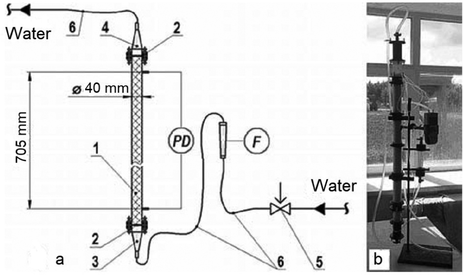
Experimental set-up: a. Installation diagram; b. Column (photograph); 1 – column with sorbent; 2 – filters; 3 – inlet chamber; 4 – outlet chamber; 5 – control valve; 6 – flexible pipes; PD – pressure difference gage; F – flow meter. |
|
||||||||
| Part of: Tashlykov OL, Bessonov IA, Lezov AD, Chalpanov SV, Smykov MS, Skvortsov GI, Klimova VA (2022) Computational and experimental studies into the hydrodynamic operation conditions of container filters for ion-selective treatment. Nuclear Energy and Technology 8(3): 197-202. https://doi.org/10.3897/nucet.8.94105 |