|
||
|
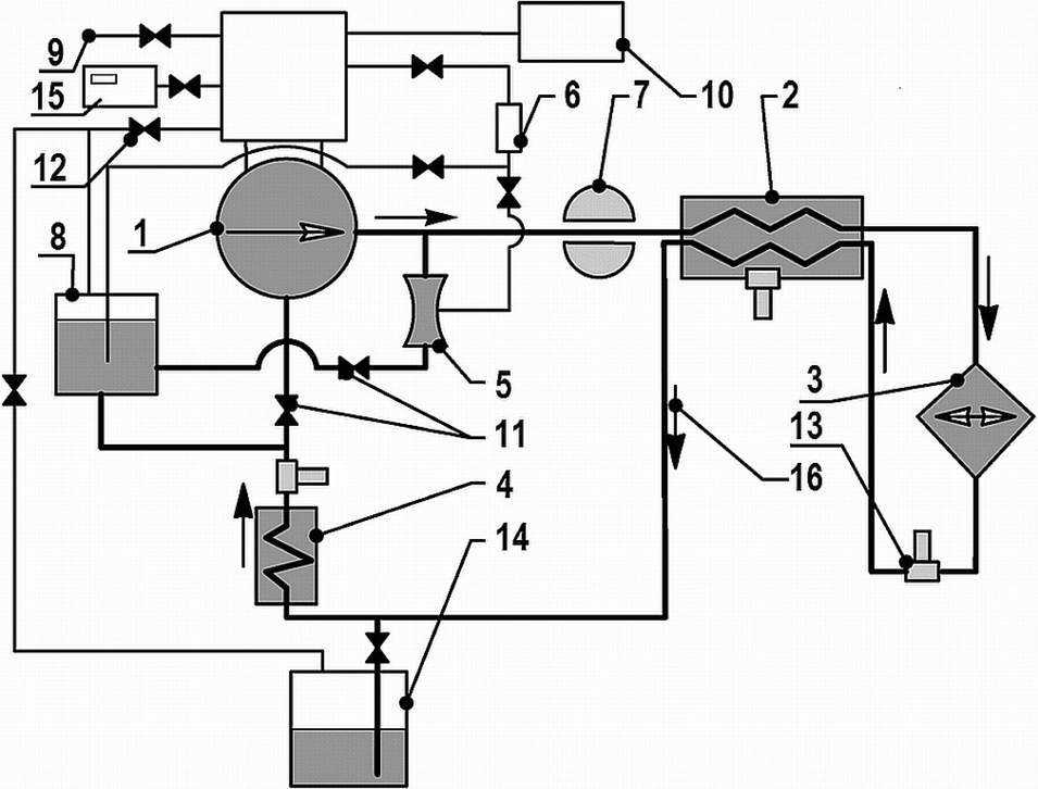
Layout of the TT-2M test facility circulation circuit: 1 – circulation pump; 2 – recuperative heat exchangers; 3 – core simulating heater; 4 – steam generator simulating chiller; 5 – ejector for gas mixture injection into coolant; 6 – water evaporator; 7 – coolant flow meter; 8 – coolant volume change compensator; 9 – gas circuit connection to gas supply and vacuum system; 10 – gas composition monitoring system; 11 – liquid metal valves; 12 – gas valves; 13 – oxygen activity sensors of zirconium dioxide; 14 – coolant storage and melting tank; 15 – gas flow meter; 16 – coolant flow direction. |