|
||
|
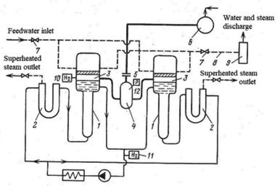
Flow diagram of the Field-tube SG APS: 1 – evaporator; 2 –superheater; 3 – gas space; 4 – stage I separator; 5 – gas space rupture disk; 6 – stage II separator; 7 – fast-acting steam-water valves; 8 – emergen- cy water discharge line; 9 – expansion tank; 10 – hydrogen-in-gas detector; 11 – hydrogen-in-sodium detector; 12 – gas space pressure gage. |