|
||
|
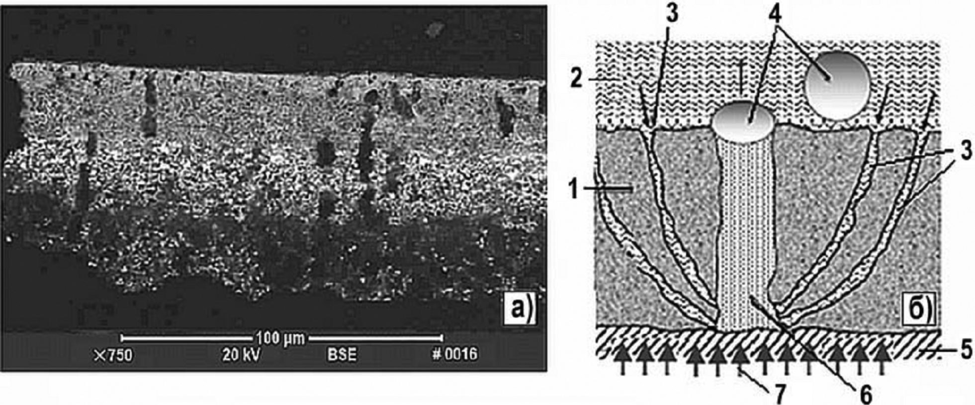
Steam channels in deposits in high-energy areas of the PWR FA fuel rod surface a. A photograph with three regions (intermediate, light – ZrO2) (Henshaw et al. 2006); b. Idealized diagram: 1 – oxides; 2 – coolant; 3 – water channel; 4 – steam bubbles; 5 – fuel cladding; 6 – steam channel, 7 – heat supply (Kritsky et al. 2011). |